
PrimerFusion Science 301
Another image view shows the magnetic orientation of the fields within the bowl-shaped magnetic array. The ejection jet is indicated by the green arrows. The Flip Ring is yellow, and the Confinement Dome is shown in magenta. At the Flip Ring, the magnetic polarity suddenly “Flips” which is why it is called the “Flip Ring”. The Confinement Dome “Confines” the plasma underneath it until enough energy is applied and then the plasma is ejected up through the ejection jet. The only way for plasma to go from above the Confinement Dome to below it is for the plasma to first go through the Flip Ring.

This is a 3D view of the bowl-shaped magnetic array showing the Confinement Dome in magenta and the Flip Ring in yellow.
The location of the Flip Ring.

The base of the Confinement Dome is on the Flip Ring.
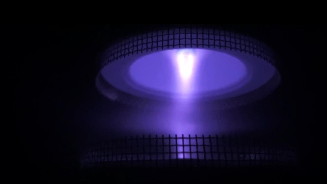
This image shows two identical bowl-shaped magnetic arrays in a PrimerFusion reactor.
This image shows the electrical circuit and plasma flows within a PrimerFusion reactor.
The electrical circuit and plasma flow in a PrimerFusion reactor. The Emitter electrode is positive electrically and the Collector Screen which surrounds the top of the bowl-shaped magnetic array is negative electrically in normal reactor operation. The green arrows indicate the plasma and electrical flow from the Emitter (+) to the Collector Screen (-). The white arrows show the plasma and electrical flow from the Collector Screen to the Flip Ring. The red arrows show the plasma and electrical flow from the Flip Ring to the Emitter. The top of the PrimerFusion reactor is identical to the lower half shown in this image.
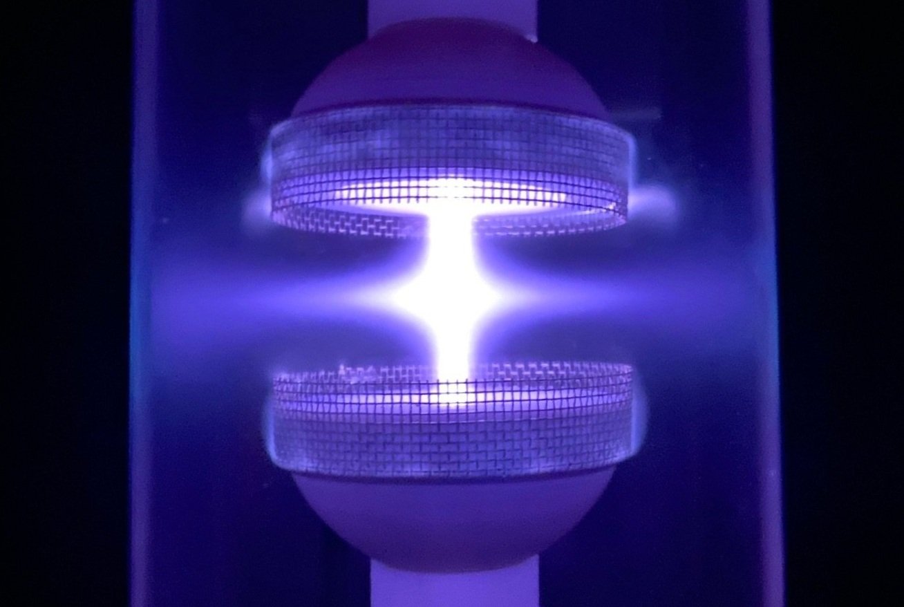
The top and the bottom of the PrimerFusion reactor in this image are identical. The PrimerFusion reactor currently under construction will use a horizontal arrangement instead of the vertical arrangement shown here. Fusion reactions begin in the Fusion Initialization zones. We hope to see secondary fusion reactions in the middle of our new PrimerFusion reactor due to increased magnetic flux density and greatly increased energy input.
This overlay animation shows the plasma particle flow from the Collector Screen to the Flip Ring.
The yellow particles represent the plasma particle flow from the Flip Ring to the Emitter. As you can see all of the energy contained within the plasma is focused back to the Emitter. I believe that within this area, the Hydrogen Boron plasma particles undergo constructive and destructive interference, which allows fusion to occur at much lower energies than previously believed possible. This is how the PrimerFusion process is related to the double-slit experiment and the constructive and destructive interference we see in that experiment whether it uses photons of light or electrons. Matter can interfere with matter just as photons of light interfere with each other. I believe that the key to achieving fusion with lower energies than previously believed possible is through the matter interference that occurs in a PrimerFusion reactor. Normally the nuclei of Hydrogen and Boron repel each other due to the alignment of the fields that surround those nuclei. Within the bowl-shaped magnetic arrays in a PrimerFusion reactor, the magnetic alignment of those fields is altered so that the nuclei of the Hydrogen and Boron no longer repel each other as strongly as they normally would. In other words, the Coulomb Barrier can be overcome with far lower energy levels in a PrimerFusion reactor than is possible otherwise. This is the key to PrimerFusion.
The green particles indicate the plasma particle flow that occurs when the energy forces the particles above the Confinement Dome where they are accelerated up the ejection jet zone. In a PrimerFusion reactor, the jets from the two opposing bowl-shaped magnetic arrays are directed into each other, as shown below.
The plasma particles flow in a continuous pattern that is very efficient. As you can see the electrical flow goes from the emitter and returns to the Collector Screens. The Collector Screens are connected to a conductor that passes through an Energy Capture Transformer on the return to the negative side of the high-voltage power supplies. That Energy Capture Transformer draws the excess energy produced by the Hydrogen Boron fusion reaction within the PrimerFusion reactor.
This is a diagram of the energy flows in a PrimerFusion system. The only moving parts are in the vacuum pump, cooling system, and mass flow controller. The pink lines indicate control system connections. The negative (black) returns to the high-voltage power supplies pass through the Energy Capture Transformers which extract the excess energy produced by Hydrogen Boron fusion. The Energy Capture Transformer connects to the Power Regulation Module which distributes the electricity to the Battery Pack, Back to the Reactor System, provides output power for local use, or supplies excess electricity produced by the PrimerFusion system to the power grid if so desired. The PrimerFusion system currently under construction will not be connected to any input power. It is designed to start and operate stand-alone as the diagram above illustrates.